Lesson reading
live
55 min
Start with the lesson question, connect the representations, and test the model with evidence.
Inspect the opening phenomenon
Predict what changes, then name the evidence.
Apply in the lab
Name the evidence before reading the answer.
Read only what helps
Then use the lab and recall check.
More when needed
Transcript and resources stay available below.
Course progress
Images, Depth, and Features
Decision challenge
Use the opening example to make a prediction, identify evidence, and explain which model supports it.
A camera measures arrays; calibrated depth and features become testable evidence.
A camera measures arrays; calibrated depth and features become testable evidence.
Lesson reading
live
55 min
Video script
draft
Transcript fallback
available
courses/ai-robotics/modules/06-robot-perception-and-computer-vision/lessons/01-images-depth-and-features/video-transcript.md
From Pixel to 3D Evidence
draft
25 min
Mastery check
live
6 questions / 10 min
# Transcript Does a robot camera see objects? No. It receives arrays of measurements. An RGB pixel stores channel values at row v and column u. A depth pixel can add distance Z, but zero or missing depth is not geometry. Calibration supplies focal lengths and the principal point. Together, pixel and valid depth back-project to X, Y, Z in the camera frame. Edges react to change. Corners change in two directions, making useful anchors across frames. But a feature is evidence, not an object. Check encoding, time, frame, alignment, and validity before the robot acts. Which input is missing before a pixel can become a metric 3D point? Continue the worked example on EduQuest.
Reading lab
Connect the lesson's words, diagrams, graphs, evidence, and equations.
Does a robot camera see a chair? No. It receives measurements: an image grid, perhaps a depth value for each pixel, and metadata describing when and where those measurements were taken. Software must turn that evidence into useful estimates.
(u, v) stores encoded channel values such as red, green, and blue. Resolution adds samples, not guaranteed understanding.ROS sensor_msgs/Image records height, width, encoding, row step, data, timestamp, and camera frame. The encoding matters: the same bytes mean different things under RGB, grayscale, or depth encodings.
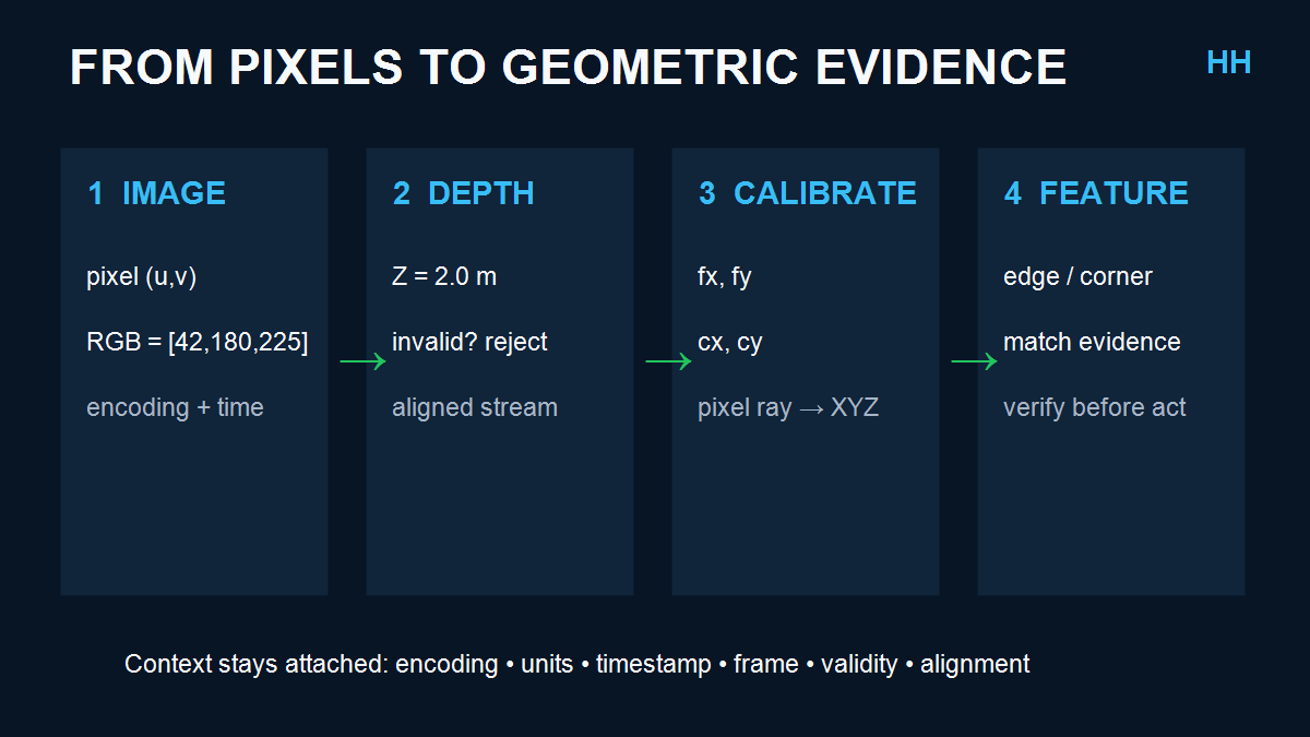
Assume an aligned depth image reports Z = 2.0 m at pixel (u, v) = (420, 290). Camera calibration gives fx = fy = 500 px and principal point (cx, cy) = (320, 240).
For a pinhole camera:
[ X=(u-c_x)Z/f_x, \qquad Y=(v-c_y)Z/f_y ]
So X = 0.40 m, Y = 0.20 m, and Z = 2.0 m in the camera optical frame. This is meaningful only when the depth and color pixels are aligned, the intrinsics match the stream, units are known, and the reading is valid.
Retrieval pause: If
Zdoubles while the pixel and intrinsics stay fixed, what happens toXandY? They double too.
A flat patch may look nearly identical after a small camera motion. A corner changes strongly in two image directions, so it can be localized and matched more reliably. Edges help describe boundaries but can slide along their own direction. Blur, lighting, viewpoint, and repeated texture can still break matches.
| Evidence | Useful for | Common failure |
|---|---|---|
| RGB values | appearance and color contrast | illumination and exposure change |
| Depth | scale and obstacle geometry | holes, range limits, reflective surfaces |
| Edge | boundary evidence | weak contrast or blur |
| Corner/keypoint | matching across frames | repeated texture or occlusion |
Before a robot acts, ask: What is the encoding? Which timestamp and frame apply? Is depth valid and aligned? Are features repeatable under expected lighting and motion? What fallback handles missing evidence?
Images are encoded grids; depth adds metric evidence; calibration connects pixels to rays; features provide repeatable anchors. Reliable perception preserves the measurement’s frame, time, units, and uncertainty.
Back-project valid depth pixels and distinguish measurements from inferred features.
lab-worksheet.csvfx = fy = 500, cx = 320, and cy = 240.X=(u-cx)Z/fx and Y=(v-cy)Z/fy.The center pixel projects to X=0, Y=0; off-center points shift laterally with depth. Invalid depth produces no trustworthy 3D point.
Change fx from 500 to 700 and explain why the same pixel projects closer to the optical axis.
All values and formulas are provided as text. Learners may describe direction and validity without drawing the image.