Lesson reading
live
45 min
Start with the lesson question, connect the representations, and test the model with evidence.
Inspect the opening phenomenon
Predict what changes, then name the evidence.
Apply in the lab
Name the evidence before reading the answer.
Read only what helps
Then use the lab and recall check.
More when needed
Transcript and resources stay available below.
Course progress
Actuators and End Effectors
Decision challenge
Use the opening example to make a prediction, identify evidence, and explain which model supports it.
Predict why more torque or grip force may reduce safety.
More torque or grip force can reduce safety when contact and payload evidence are missing.
Before
Predict why more torque or grip force may reduce safety.
During
Track commands forward and measured evidence backward.
After
Name three facts the robot must verify before contact.
Lesson reading
live
45 min
Video script
draft
Transcript fallback
available
courses/ai-robotics/modules/02-robot-bodies-sensors-actuators-compute/lessons/03-actuators-and-end-effectors/video-transcript.md
Action-Chain Design Lab
draft
25 min
Mastery check
live
6 questions / 10 min
# Video Transcript Can a robot grip harder and become less safe? Absolutely. A robot acts through a chain: command, drive, actuator, transmission, joint, end effector, contact—and feedback back to the controller. The actuator converts energy into motion. The transmission trades speed for torque. The end effector touches the task. A high gear ratio may help lift a load, but it slows the joint and can amplify damaging contact. A stronger grip can crush a beaker. Rated payload is not enough; tool mass, center of gravity, inertia, and pose matter. Before the robot moves, name three facts it must verify. Limits, current state, and contact or task-success evidence—with a safe stop if any becomes stale. Continue the full AI Robotics learning path on EduQuest. Subscribe to Humanoid Hub for the next lesson.
Reading lab
Connect the lesson's words, diagrams, graphs, evidence, and equations.
Opening challenge: A gripper closes on a glass beaker. What must the robot know before “close” becomes a safe physical action?
An actuator converts supplied energy and a command into physical effort and motion. An end effector is the task-facing device at the end of the chain: a gripper, suction cup, tool, wheel, foot, or other interface with the world.
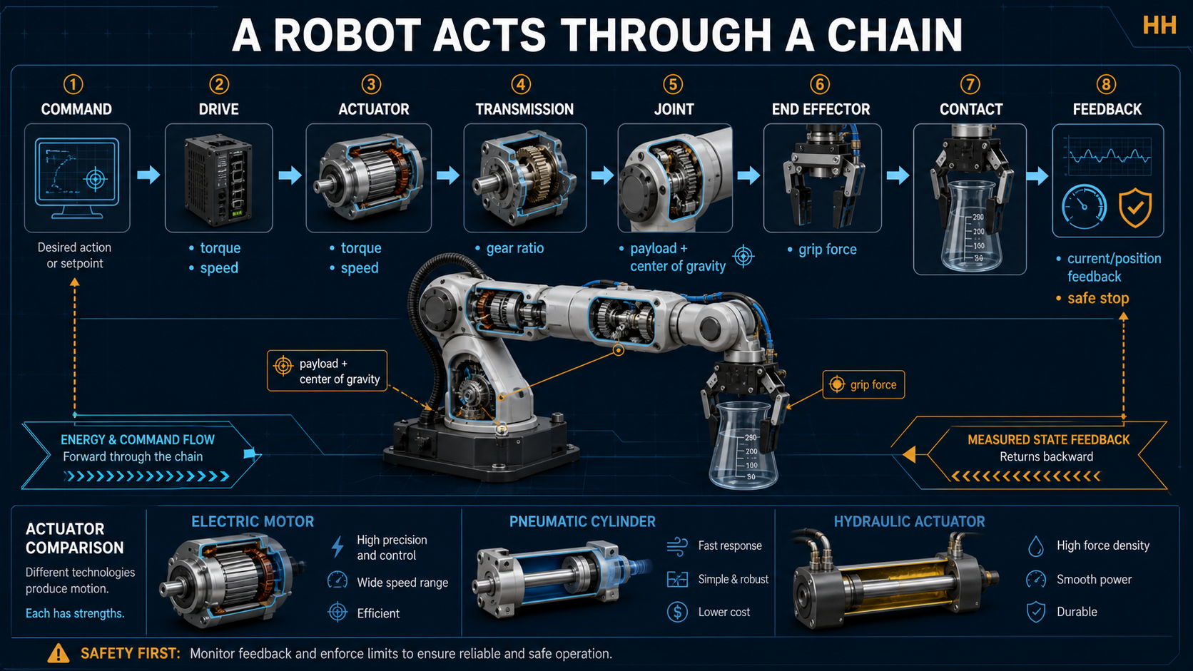
command → drive → actuator → transmission → joint → end effector → contact
   ↑                                                                    ↓
   └──────────── measured position, speed, effort, current, contact ─────┘
The chain matters because a correct high-level command can still fail through insufficient torque, excessive speed, backlash, wrong payload data, a poor tool, uncertain contact, or stale feedback.
| Technology | Converts | Typical strength | Typical trade-off |
|---|---|---|---|
| Electric motor | electrical energy to rotation | precise, wide control range | heat, gearing, current limits |
| Pneumatic cylinder | compressed-air pressure to linear motion | fast and mechanically simple | compressibility complicates precise force/position |
| Hydraulic actuator | fluid pressure to force/motion | high force density | pumps, leaks, maintenance, fluid hazards |
ROS 2 control represents robot hardware with command interfaces and state interfaces. A controller may command position, velocity, or effort while reading the resulting state. “Command sent” is therefore not evidence that motion or contact succeeded.
A transmission maps actuator motion and effort into joint motion and effort. Ideal mechanical power is approximately conserved:
where is torque and is angular speed. Gearing can raise output torque while reducing output speed. Real transmissions also add friction, compliance, backlash, heat, and efficiency losses.
A motor can supply through a 20:1 reduction. Ignoring losses, the output torque is about:
At 80% efficiency, a better estimate is . The joint rotates about twenty times slower than the motor. This may help lift a load but may make the action too slow—or amplify collision forces if limits and feedback are poorly designed.
Choose from evidence, not appearance:
Universal Robots requires payload, center of gravity, and inertia information for optimal robot behavior. Picking and releasing an object changes the active payload. A tool that can hold the mass may still overload the arm when the center of gravity is far from the flange.
A decision-ready action contract includes command mode, valid range, maximum speed/effort, expected state update rate, stale-state threshold, contact criterion, stop behavior, and reset conditions. ROS 2 hardware lifecycle states separate configuration, activation, deactivation, shutdown, and error handling; movement interfaces should not be treated as always available.
End-effector safety is also an integration problem, not merely a component rating. ISO/TR 20218-1 provides specific guidance for designing and integrating robot-system end effectors, complementing the broader ISO 10218 robot and application safety requirements. This lesson teaches the engineering evidence needed for reasoning; it does not replace a task-specific risk assessment or the applicable standards.
“The motor is the actuator, transmission, and joint.” These are separate roles even when packaged together.
“More grip force is always safer.” Excess force can crush, deform, launch, or damage an object.
For example, Robotiq's 2F gripper control interface treats requested position, speed, and force as separate settings. Its force setting limits motor current, and exceeding that limit stops the fingers and triggers object-detection status. That is concrete evidence that “grip harder” is not a complete control strategy: the robot must also observe state and contact outcome.
“Rated payload proves every pose is safe.” Reach, center-of-gravity offset, inertia, acceleration, tool mass, and orientation all matter.
“Position control guarantees safe contact.” Contact also depends on force, compliance, geometry, sensing, and stopping behavior.
Robots act through a coupled chain. Select the actuator technology, transmission, joint, and end effector together; verify payload and contact assumptions; read state rather than trusting commands; and define limits and safe stopping before physical execution.
Choose and justify an actuator, transmission, and end effector for a fragile-object transfer without requiring hardware.
Use paper or a spreadsheet. Mission: move a 0.40 kg glass container 0.30 m, place it within 10 mm, and stop safely if grip evidence is lost.
A comparison table, annotated chain, calculations with assumptions, selected design, rejection rationale, acceptance tests, and safe fallback.
Which assumption most threatens the design? What sensor or test would reduce that uncertainty?
Change the object to a flexible pouch or porous box. Re-evaluate the end effector, sensing, force limits, failure behavior, and acceptance evidence; explain which earlier assumptions no longer hold.
All work may be submitted as structured text. Do not test gripping on people, animals, glass, powered machinery, pressurized systems, or unsecured robots. ISO 10218-2:2025 addresses integration across design, commissioning, operation, maintenance, and decommissioning of industrial robot applications; this paper exercise is educational evidence, not a risk assessment or certification.
Primary reference: ISO, ISO 10218-2:2025 — Industrial robot applications and robot cells, official scope and lifecycle summary; retrieved 2026-08-18. The paid standard text was not reproduced.