Lesson reading
live
1 hr
Start with the lesson question, connect the representations, and test the model with evidence.
Inspect the opening phenomenon
Predict what changes, then name the evidence.
Apply in the lab
Name the evidence before reading the answer.
Read only what helps
Then use the lab and recall check.
More when needed
Transcript and resources stay available below.
Course progress
Grasping, Reachability, and Contact
Decision challenge
Use the opening example to make a prediction, identify evidence, and explain which model supports it.
Why Does a Robot Drop an Object It Can Reach? Grasping
Why Does a Robot Drop an Object It Can Reach? Grasping
Lesson reading
live
1 hr
Video script
approved
Transcript fallback
available
courses/ai-robotics/modules/09-manipulation-and-human-robot-interaction/lessons/01-grasping-reachability-and-contact/video-transcript.md
Find the Missing Grasp Check
approved
30 min
Mastery check
live
7 questions / 8 min
Full non-video equivalent All teaching is available without sound, motion or video. Numbers and geometry are original simulation examples, not hardware settings. 00:00 — Reach it. Still drop it. Visual mechanism: Two parallel jaws close around a block, rise once and lose the block onto a support. Reach and clearance labels remain distinct from holding. Spoken explanation: Why does a robot drop an object it can reach? Reaching the object, getting there without a collision, and holding its weight are three different tests. 00:10 — Can the joints get there? Visual mechanism: A two-link planar arm extends to a one-metre radius and retracts to a reachable pose. A red target outside maximum reach remains unreachable. The freely rotating position workspace has an inner radius too. Spoken explanation: Start with reach. These two links are sixty and forty centimetres long. Their tip cannot reach beyond one metre. Inside that boundary, inverse kinematics finds candidate joint angles. But real joint limits and the required gripper orientation can still rule a candidate out. 00:31 — Check the whole motion. Visual mechanism: The direct approach stops at a detected collision. An explicitly labelled alternative route moves the entire arm around the obstacle. The example checks simplified link capsules and gripper geometry, not an attached object. Spoken explanation: Now watch the approach. The destination is reachable, but the direct move hits an obstacle. A clear endpoint is not a clear path. Check the arm links and the gripper along the entire approach, then check the retreat with the object attached. 00:49 — Touching is not holding. Visual mechanism: A contact-force schematic shows inward normal forces, upward friction and downward weight. Friction capacity is labelled as a bound, not a constant applied force. Spoken explanation: At contact, each pad pushes inward. Friction opposes the object's downward slip. In this simplified model, each pad can supply at most mu times N in upward friction. Mu is the friction coefficient. N is the inward force from one pad. 01:09 — Capacity versus weight. Visual mechanism: For a 0.5 kg block, the comparison changes from 4 N to 6 N per pad, with mu=0.5. Total capacities are 4 N and 6 N against 4.9 N weight. The first trial slips; the second passes the static vertical test. Values are not hardware settings. Spoken explanation: Our simulated object has a mass of half a kilogram, so its weight is about four point nine newtons. With mu equal to one half and four newtons from each pad, total friction capacity is four newtons. It slips. At six newtons per pad, capacity is six newtons. The static weight test passes. 01:31 — More squeeze has a limit. Visual mechanism: An invented 5 N-per-pad damage limit rejects the 6 N squeeze. The block rests on a support and the jaws are open. The narration names torque, uncertainty and actuator limits. Spoken explanation: That is not a safety certificate. A fragile object might be damaged by the extra squeeze. Real grasps must also handle torque, acceleration, uncertain friction, and actuator limits. Two ideal point contacts do not guarantee full three dimensional force closure. 01:51 — Which test is missing? Visual mechanism: A slipped object rests on a support. Learners choose reach, clearance or contact and consider whether more squeeze is appropriate. A three-second quiet retrieval pause precedes the answer. Spoken explanation: Your turn. A planner finds joint angles and a collision free approach. The object still slips. Which test was missing: reach, clearance, or contact forces? And should the robot simply keep increasing its squeeze? 02:09 — Reach. Clear. Hold. Visual mechanism: The three evidence checks illuminate in order. A block moves onto a support to illustrate revising the task instead of escalating force. The narration invites the simulation and quiz. Spoken explanation: Contact forces. Compare available friction with the load, and respect damage and actuator limits. If a safe force is not enough, change the grasp, support the object, or stop for help. Try the simulation and quiz in the Humanoid Hub AI Robotics course.
Reading lab
Connect the lesson's words, diagrams, graphs, evidence, and equations.
The camera recognizes a block. The robot reaches it. The fingers close. The block falls. Which part of the reasoning failed?
Recognition, reachability, clearance and holding are different achievements. This lesson asks you to diagnose them separately before calling a grasp successful.
By the end, you can:
Prerequisites: position and orientation, forward/inverse kinematics, and collision-aware planning. Watch the complete Humanoid Hub tutorial, or use the complete descriptive transcript for an equivalent non-video route.
Allow about 8 minutes for the 2:30 tutorial, pauses and a short explanation. This is ungraded practice before the lab and quiz. You do not need to finish a calculation during the video's short pause.
At 00:00, a reachable object falls after the fingers close. Write one possible cause and one piece of evidence that would distinguish it from a collision or reachability problem. Keep this first prediction so you can revise it later.
Times are approximate scene starts in the preserved full tutorial. Watch once for the story; on a second pass, pause at the relevant checkpoint.
| Start | Look for | Explain or predict before continuing |
|---|---|---|
| 00:10 — Reach | The arm extends toward a target. | What does adding the two link lengths rule out? What does it leave untested? |
| 00:31 — Clearance | The direct approach stops; the alternative route moves the arm around the obstacle. | Why is testing only the final fingertip position insufficient? Separate the simulated approach from the carried-object retreat that the narration says must also be checked. |
| 00:49 — Contact | Inward pad forces and vertical forces point in different directions. | Which force is N? Why are there two contributions to upward friction capacity? |
| 01:09 — Worked example | Capacity changes while the same object's weight stays fixed. | Calculate capacity and weight separately. If the object is motionless, is actual upward friction the weight or the maximum capacity? |
| 01:31 — Limits | The invented damage limit rejects the higher squeeze. | Which constraint now prevents accepting the grasp, even after the weight test passes? |
| 01:51 — Your turn | The question separates reach, clearance and contact. | Name the missing evidence and explain why increasing squeeze is not automatically acceptable. Pause by 02:09 if you need more thinking time. |
| 02:09 — Explanation | The example returns to the three checks and revising the task. | Compare the explanation with your prediction. Identify one change in your reasoning. |
Without video: use the same timestamped headings in the descriptive transcript. Read each visual mechanism and spoken explanation, answer the corresponding prompt, then move to the next heading. Stop before “02:09 — Reach. Clear. Hold.” until you have attempted the question. Written, spoken or sketched responses are equally useful; no timed response is required.
For a new simulated object, keep the symmetric static model but use mass 0.6 kg, mu 0.4, and 6 N per pad. Does the vertical load test pass? Show both quantities with units, then state one thing this test cannot establish. Finally, suppose the object's invented limit is 5 N per pad: is the chosen squeeze permitted by that limit?
Capacity is 2 * 0.4 * 6 = 4.8 N; weight is 0.6 * 9.81 = 5.886 N. Capacity is insufficient in this model. Separately, 6 N per pad exceeds the invented 5 N-per-pad limit. A successful vertical test would still not establish collision clearance, resistance to every torque, or real-hardware safety. If you compared just one pad's capacity with the whole weight, revisit the contact scene; if you changed the weight when changing squeeze, revisit the worked example.
Now revise your opening prediction using evidence, and take that explanation into the Practice lab. Complete the quiz only after the lab; keep the self-check above distinct from the graded quiz answers.
| Check | Evidence you need | What a pass does not establish |
|---|---|---|
| Reach | A pose satisfying kinematics, joint limits and tool orientation | A collision-free route |
| Clear | Collision checks along approach and retreat, including arm, tool and carried object | Sufficient contact forces |
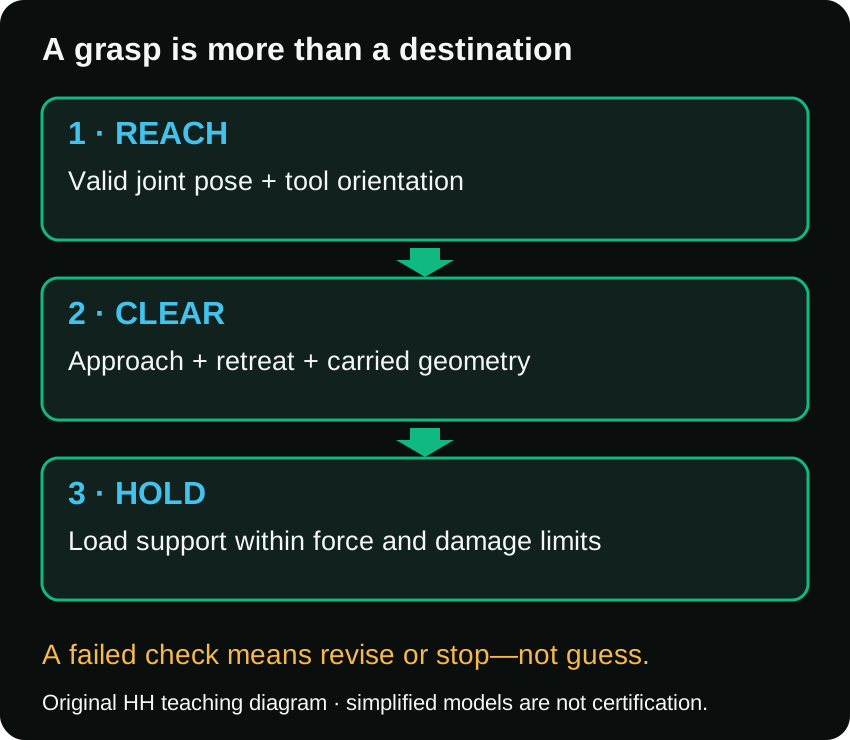
| Hold | Load-supporting contact forces within friction, actuator and object limits | Every disturbance is safe |
For our freely rotating planar two-link arm, lengths are 0.6 m and 0.4 m. A tip position at radius 1.06 m is impossible: the links only add up to 1.0 m. A point closer than 0.2 m is also unreachable in this ideal model, because the unequal links cannot fold their lengths away completely.
Thus the position workspace is an annulus, 0.2 <= r <= 1.0 m. This is our original triangle-geometry example, not a robot specification.
Inverse kinematics finds joint angles for a target. Two elbow arrangements can reach many of the same positions. Neither existence nor solver success alone proves that a required wrist orientation or real joint limit is satisfied. MIT's pick-and-place chapter develops the relationship between configuration and gripper pose.
Predict: Does a reachable center point prove a wide gripper can enter a narrow shelf? No: pose, tool geometry and the approach still matter.
Run the original model. The direct route ends at a reachable position but fails the obstacle test before arriving. Even changing the fingertip route can leave the elbow or forearm in collision.
The supplied detour checks 1,001 poses against a circular obstacle, using two link capsules and a circular gripper envelope. Its smallest sampled clearance is approximately 0.0269 m. That is evidence about this model and sampling—not a continuous collision certificate, a tolerance recommendation, or a complete real-robot plan. The model intentionally omits joint limits, wrist orientation and self-collision.
MoveIt's Planning Scene tutorial distinguishes environment/self-collision checks and kinematic constraints. Our lab is independent original code, not MoveIt.
After grasping, the collision geometry changes: the carried object becomes part of what must clear the surroundings. Check retreat too. The video reminds you of this requirement but does not simulate full carried-object collision geometry.
Imagine a centered 0.5 kg block between two vertical pads. Each pad pushes inward with normal force N. The assumed dry-friction coefficient is mu. Each pad's upward friction capacity is mu * N, so the combined capacity is 2 * mu * N.
For a slow, symmetric vertical lift:
2 * mu * N >= m * g
N means the force from one pad, not the total squeeze from both. With g = 9.81 m/s², weight is 0.5*9.81 = 4.905 N, about 4.9 N.
| Simulation case | mu | N per pad | Capacity 2 * mu * N | Result for weight alone |
|---|---|---|---|---|
| A | 0.5 | 4 N | 4 N | Insufficient; slip is expected |
| B | 0.5 | 6 N | 6 N | Static vertical test passes |
| C | 0.3 | 6 N | 3.6 N | Insufficient with lower friction |
Friction is not always equal to its maximum. While case B holds the block motionless, total upward friction balances 4.905 N, not 6 N. The remaining capacity is a model margin. See Modern Robotics: Friction for the approximate contact law.
Retrieve: If mass doubles but mu and N stay fixed, which side changes? Weight doubles to 9.81 N; capacity stays 6 N. The previous pass becomes a failure.
Add an invented damage limit of 5 N per pad. Case B requires 6 N per pad, so it must be rejected even though the weight calculation passes. A stronger actuator does not remove the object's limit.
Try changing grasp geometry, using suitable support, reducing the task demand, or stopping for assistance within an approved operating procedure. This simulation does not prescribe hardware force settings.
Real lifting also involves acceleration, torque, contact patches, compliance and uncertain surface conditions. A centered static calculation does not address all of them. MIT's contact treatment separates force and torque balance.
Do not call this a full three-dimensional force-closure test. Two ideal point contacts leave a rotation about their connecting axis unrestrained. Soft contact patches may supply additional moments, but that is a different model. Modern Robotics: Force Closure also explains why a geometric force-closure property does not remove actuator limits.
A planner finds joint angles and a collision-free approach. The block slips.
A strong answer identifies contact forces, compares available friction with load, and checks object/actuator limits. It also states whether torque, motion and uncertainty were considered.
Complete the Practice lab, including the no-code worksheet, then the seven-question quiz. Keep your predictions, measured/calculated evidence and revised explanations.
In one sentence: reach tells you whether a pose is available; clearance tells you whether the motion fits; contact analysis tells you whether the grasp can support the intended load within its limits.
Time: 25–30 minutes inside the 60-minute lesson. Simulation only. No robot, paid software or account required.
Identify the missing evidence in a failed grasp using reach, clearance and force checks.
Paper and calculator, or the downloadable standalone model and Node.js. No robot, paid service or account is required.
Will reaching a target and planning a clear approach guarantee a successful lift? Write your prediction before running anything.
node model.mjs. The file is independent of external packages.Complete Parts A and B, record predictions before calculating, then use Part C to explain the model's limits. Keep your calculation table as evidence.
Expected: 1.0 m outer and 0.2 m inner radius; the first two targets fail, the third has position solutions in the freely rotating model. The direct route collides; its first sampled collision is near fraction 0.317. The detour passes the simplified sampled check with about 0.0269 m minimum clearance. Do not transfer that number into hardware settings.
The model checks arm-link capsules and a circular gripper. It omits self-collision, joint limits, prescribed wrist orientation and carried-object geometry. List two additional checks needed before a real retreat.
Use weight = m * 9.81 and capacity = 2 * mu * N. N is per pad.
| Trial | mass kg | mu | N per pad | extra limit / demand | Your prediction |
|---|---|---|---|---|---|
| A | 0.5 | 0.5 | 4 | no added model limit | |
| B | 0.5 | 0.5 | 6 | no added model limit | |
| C | 0.5 | 0.3 | 6 | no added model limit | |
| D | 0.5 | 0.5 | 6 | damage limit 5 N/pad | |
| E | 1.0 | 0.5 | 6 | no added model limit | |
| F | 0.5 | 0.5 | 6 | upward acceleration 4 m/s² |
For F, use load = m * (9.81 + a). These are invented simulation inputs, not operating recommendations.
Expected evidence: A: capacity4 < load4.905, fails. B: 6 > 4.905, static test passes. C: 3.6 < 4.905, fails. D: capacity suffices but allowed squeeze is exceeded, reject. E: 6 < 9.81, fails. F: 6 < 6.905, fails.
Find the ideal minimum N for trial B's mass and friction. N=4.905 N per pad exactly balances the weight in this model. Why is an exact boundary without uncertainty margin a poor real-world acceptance rule? Do not invent a universal margin.
Now answer: can two ideal point contacts guarantee full 3D force closure? No. Explain the unresisted rotation about the line joining the points. This is not tested by the scalar vertical equation.
A completed table; one failed prediction corrected using evidence; the difference between capacity and actual static friction; two model omissions; and a proposed response when the object or actuator limit prevents enough grip.
What evidence would you gather if a simulated success repeatedly failed on a real object? Discuss sensing, friction uncertainty, contact geometry and load dynamics; do not propose bypassing interlocks or unrestricted force increases.
For the ideal two-link model, the position radius lies between 0.2 and 1.0 m. A reachable endpoint does not prove a clear path. The supplied simulation reports 1776 assertions. Trials A, C, E and F lack capacity; B passes the static vertical load test only; D exceeds its invented damage limit. The paper worksheet tests equivalent reasoning.
Design a case where vertical capacity suffices but acceleration, contact geometry or an object limit rejects the grasp. Explain the omitted evidence. Do not connect this model to hardware.